Unfolding
There are several steps to successfully unfolding the high resolution scans of the hippocampus. The details for this section fall into the broad categories of segmentation, interpolation, demarcations, and calculating thickness. A knowledge of command line is necessary, as well as obtaining the tools for each step.
Tools Required
- A copy of Windows
- A virtual machine emulator
- A command line interface to connect to hoffman
- MrGray (Windows only)
- Matlab
Segmentation
Overview
The goal of segmentation is to create a strip of gray matter in the hippocampus by locating the boundaries of the hippocampus in the brain. Using FMRI technology, the brain is sliced anteriorly to posteriorly to obtain slices of all parts of the hippocampus, creating a 2D version of the 3D hippocampus that can be mapped and analyzed. After opening VirtualBox, we run a computer program, MrGray Segmentation software for Windows, where we can view and find all the slices of the brain that show a portion of the hippocampus. On these slices,the hippocampal gray matter is surrounded by white matter and cerebral spinal fluid (CSF). We must mark the surrounding white matter and CSF respectively to obtain our strip of gray matter in between. The CSF material is the strip of atrophy on the interior of the gray matter, which begins at the hippocampal fissure, follows down to the collateral sulcus, and finishes after the second sulcus. The white matter is the material on the exterior portion of the gray matter. It is important to note that the shape of the hippocampal head changes from anterior to posterior in the brain. On the anterior slices, the hippocampal head has a long, oval shape. In the posterior slices, the hippocampal head has a round, almond shape. On the anterior slices, the CSF matter comes up to meet the white matter at the hippocampus head and also continues through the second sulcus through the gray matter to close off our strip. In the posterior slices, the CSF still continues through the second sulcus to the gray matter to close off the strip, but the white matter comes down to the CSF at the hippocampal fissure on the hippocampal head.
Creating Segmentation Files
Segmentation files are created by first creating vAnatomy.dat files in Matlab. To open Matlab in Terminal you must be logged into hoffman. Once you are logged on, you will run these commands in Terminal:
- 1. qrsh -l i,h_rt=5:00:00,h_data=4G
- The "5:00:00" indicates that Matlab will run for 5 hours.
- 2. module load matlab/7.14
- 3. matlab
- 1. qrsh -l i,h_rt=5:00:00,h_data=4G
To create the vAnatomy.dat file and prepare the high resolution T2 images, you will run these following commands in Matlab:
- 1. addpath(genpath('/u/home/FMRI/apps/unfolding/current/'));
- Note: The warning message can be ignored.
- 2. cd /u/project/sbook/data/AD/subjects/AD_1XXXX/20######/analysis/structural/unfold
- X's denote the subject number and # indicates scan date. Running this command will take you to the subject's unfold directory.
- 3. NLF_InitVol
- This command will begin initializing the volume anatomy file.
- 4. In the window that appears, navigate to the subject's "nii" directory of NIfTI volume image files and select the "hhr_struct" file.
- 5. Another window with the image scan of the subject will appear. Begin drawing a rectangular box around the hippocampal region, covering both the left and right sides.
- Note: It is important to draw the rectangle with enough vertical space above and below the region to account for positional differences of the hippocampal region across different slides.
- 6. Once the box has been drawn, double click inside the drawn region and Matlab will begin initializing the file.
- 1. addpath(genpath('/u/home/FMRI/apps/unfolding/current/'));
Getting Started: The Initial Segmentation Checklist
- Export all of your vAnatomyCrop.dat files to a PC (ftp using binary).
- Run the program mrGray
- Create a new project and name it after your subject. Use the following nomenclature:
- AD_#####
- ex. AD_12345
- AD_#####
For a subject with the Small ID 12345, who was scanned on May 25th, 2012, the following would be the subject entry in /u/home/data/sbook/data/AD/subjects:
- subj ID: AD_12345
- date: 20120525 (yyyymmdd)
- And it would be in the following path:
- /u/home/sbook/data/AD/subjects/AD_12345/20120525/... etc etc.
Subjects file names should look like:
- subject ID: AD_12345
- subject scan date: 20120525
- segmentation: AD_12345_seg
- interpolation: AD_12345_interpright or AD_12345_interpleft
Once you have completed the segmentation session make sure to update our filemaker tab in objective fitness spreadsheet
- Select name for new project in AD/subjects/AD_XXXXX/SCANDATE/analysis/structural/unfold/segmentation
- Select vAnatomyCrop.dat
- Figure out which slices to segment based on anatomical guidelines.
- Anteriorly, choosing the last slice in which hippocampal head is visible is a consistent start point we've used
- Select name for new project in AD/subjects/AD_XXXXX/SCANDATE/analysis/structural/unfold/segmentation
- Below are anatomical diagrams of the hippocampus and what to look for:

- Figure 1. Anatomical diagram, with an inferior view of the whole brain at the left, an inferior view of the temporal lobe at the center, and coronal sections from the two indicated slices at the right. A: Anterior slice through entorhinal cortex. B: Posterior slice through parahippocampal cortex. ERC, entorhinal cortex; PRC, perirhinal cortex; PHC, parahippocampal cortex; FG, fusiform gyrus; Sub, subiculum; CA 1,cornu ammonis 1; CA 2,3, CA fields 2 and 3; DG, dentate gyrus; CoS, collateral sulcus.

- Figure 2. Coronal view of right side of the hippocampus. In the coronal plane the hippocampus and parahippocampal gyrus form an S-shaped configuration. The hippocampus itself consists of two interlocking C-shaped structures: the cornu ammonis and the dentate gyrus. Histologically, the hippocampus is further divided into 4 sections CA1 to CA4.
Once file is created, you may begin segmentation process:
- Segment the white matter 1st (colored in beige) (red in our lab), using a pixel size of 3 pixels minimum
- Select white matter with the checkbox at the right
- Another checkbox indicates the highlight size (use 3)
- The left mouse button highlights a pixel, and the right mouse button deselects pixels
- Then, segment the CSF (colored in yellow) (blue in our lab), imposing a thin boundary on the segmentation. (You want it thin because you will expand it after the interpolation step).
- Save the segmentation (File -> Classification -> Save as with the above nomenclature).
- Save early, save often.
Here is an example of an initial segmentation: Starting anteriorly and ending posteriorly:


Interpolation
Explain Interpolation here.
To load an existing project, when you're in MrGray, you'll click on Load project and you can select any .mrp file. These will be named AD_1XXXX_interpleft or _interpright. It will then appear and you should be able to see the CSF and white matter masks if they are selected in the toolbar.
Create a new interpolation file; these are the steps you will take:
- Open the menu and select File > New Project
- In the first window go to the subject's unfold directory (ie. ...AD/subjects/AD_1XXXX/2012####/analysis/structural/unfold/interpolation)
- Name the project AD_1XXXX_interpleft or AD_1XXXX_interpright and hit enter
- In the second window select the Volume anatomy file for the interpolation file (vAnatInterp.dat file) and hit enter
- When the image displays, you will now go to the File menu again and then to "Classification". Then click "load classification file".
- The window that pops up will ask you to select a class file. This will be AD_1XXXX_interpright or interpleft that already exists in the directory. Select the side for which you created and hit enter.
- Check to make sure the masks align correctly.
Demarcations
Getting Started
After segmentation and interpolation, demarcations create the boundaries for the different region of the hippocampus. These boundaries can be conveniently drawn using FSLview. Open your hire structural image. Be sure this is the same brain that you used for the unfolding process. It is important to note that these images are in radiological convention, so if you're drawing on the right side of the screen, this is actually the left hemisphere. Look at your notes to determine which slices were segmented and used for unfolding; only draw boundaries on the slices that have been segmented. To create a new boundary, go to the file menu and select "Create Mask." In the lower left corner, you'll see a blue "i"; click on this to re-name your boundary as needed, and to select the color you'd like to draw with. To zoom in on the MTL, first go to View/Single, and then expland the coronal image. Use the zoom tool to magnify the MTL. Click on the pencil tool, and make adjustments as desired. A brightness with typically a max of 1 and a small pencil size work best. If using a mouse, the left button draws the boundary and the ctrl+ left button erases. When saving, be sure to save to your Demarcations directory, and to use the proper naming convention. It is best to complete one boundary at a time across all slices, and then move on to the next boundary.
General Tips
Before starting to draw, you want to first identify the slice where the hippocampal head begins. It is important to note that where the hippocampal head "begins" means where it begins when going in the Posterior to Anterior direction. This slice, which will be called the hippocampal head slice throughout the rest of these instructions is where the anterior structures will start. Also, drawing shorter/smaller boundaries will reduce variability once projected onto the flat maps, giving you a straighter line. In general, boundary doesn't need to cross the entire gray matter area; keep the boundary towards the medial or superior side of things, as appropriate.
Naming Convention
Boundaries drawn on all the slices:
- Fus(Fusiform)
- CollSul(Collateral Sulcus)
- SubCA1(Subiculum-CA1)
- CA1CA23DG(CA1-CA23DG)
Boundaries drawn on anterior slices only:
- ERCSub (Entorhinal Coral- Subiculum)
- PRCERC (Perirhinal Cortex- Entorhinal Cortex)
- AntCADG (Anterior portion of CA fields and Dentate Gyrus)
- ERCPRCPHC (Boundary between anterior structures Entorhinal/Perirhinal Cortices and the posterior structure Parahippocampal Cortex)
Boundaries drawn on the posterior slices only:
- PHCSub (Parahippocampal Cortex- Subiculum)
Individual Boundaries
On each of the slices that were segmented, we must determine which boundaries to mark.
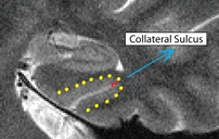
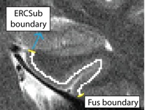
Fusiform (Fus)
- Both anterior and posterior slices
- Draw boundary perpendicular to the gray matter ribbon at the "elbow" of the lateral side of the collateral sulcus (on the side closer to the second sulcus)
- Outline of collateral sulcul shown in red; boundary between sulcus and fusiform gyrus shown in yellow
- Fusiform is lateral to the boundary

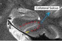
Collateral Sulcus (CollSul)
- Both anterior and posterior slices
- Draw boundary perpendicular to the gray matter ribbon at the bend in the superior tip of the collateral sulcus
- Outline of collateral sulcus shown in yellow; boundary shown in red

Separating PHC from Subiculum (PHCSub)
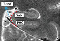
- Posterior slices only
- Begin drawing on the first slice posterior to the hippocampal head slice, and continue to draw on the remainder of the posterior slices
- Draw boundary perpendicular to the gray matter ribbon approximately 50% of the way up the bend
- Bend shown in red, boundary between subiculum and PHC shown in green
- Subiculum is superior to boundary

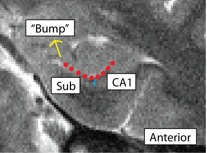
Separating Subiculum from CA1 (SubCA1)
- Both anterior and posterior slices
- Anterior: boundary more lateral; draw boundary underneath "bump" where the curve of the hippocampus comes in, bisecting it
- Bump shown in red, boundary between Sub and CA1 shown in blue
- Sub is medial to the boundary, CA1 is lateral
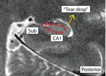
- Posterior: boundary more medial; draw boundary where the hippocampus pinches off into a tear-drop shape, or folds into itself
- Teardrop shown in red, boundary between Sub and CA1 shown in blue
- Sub is medial to the boundary, CA1 is lateral


Separating CA1 from CA23DG (CA1CA23DG)
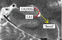
- Both anterior and posterior slices
- Draw boundary perpendicular to the gray matter ribbon at the bend (on the path where the hippocampal fissure would extend to in the hippocampal head)
- Bend shown in red; boundary between CA1CA23DG shown in green

Separating ERC from Subiculum (ERCSub)
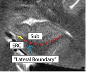
- Anterior slices only
- Begin drawing on hippocampal head slice, and continue to draw on the remainder of the anterior slices
- If you were to continue the lateral boundary of the hippocampus inwards medially, it would divide the hippocampus and the ERC
- Draw boundary along this divide, perpendicular to gray matter ribbon
- Lateral boundary shown in red, boundary between ERC and Sub shown in yellow

Separating PRC from ERC (PRCERC)
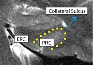
- Anterior slices only
- Begin drawing on hippocampal head slice, and continue to draw on the remainder of the anterior slices
- Draw boundary perpendicular to the gray matter ribbon at the "elbow" of the medial side of the collateral sulcus (the side of the collateral sulcus closer to the hippocampal head)
- Collateral sulcus outlined in yellow, boundary between PRC and ERC in green
- ERC medial to boundary, PRC lateral

Anterior CA fields and Dentate Gyrus (AntCADG)
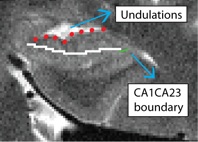
- Only one slice: draw on the first slice anterior to the hippocampal head slice (this should be the slice where you first see undulations going in the Posterior to Anterior direction)
- Draw boundary straight through middle of CADG area, and extend all the way laterally to the CA1CA23DG boundary (go through the middle of the hippocampal head between the fissure and the top of the head)
- Undulations highlighted in red; CA1CA23DG boundary in green; AntCADG boundary in white

Creating A/P boundary (ERCPRCPHC)
- Only one slice: draw on the hippocampal head slice
- Starting at the ERCSub boundary, draw a line in the middle of the gray matter ribbon up and over the collateral sulcus, all the way out to the Fus boundary
- ERCSub and Fus boundaries shown in yellow
- ERCPRCPHC boundary shown in white

Directory Outline: How to Open FSLView Through Terminal
- Below is an outline for the directory path. In order to open files for segmentation, interpolation, and demarcation in the unfolding process, you must be able to navigate the Terminal.

The best way to open FSLview in order to do demarcations is through the FSLview path in Terminal. Below are the following steps to open a file for demarcations.
- ssh -X johnsmith@hoffman2.idre.ucla.edu
- This is your login. You must have a hoffman account to access Terminal
- /u/home/FMRI/sbook/data/AD/subjects
- This is your homebase directory. Once logged into hoffman, you will be able to access the path of directories seen above.
- For each subject, there is a nii directory and a analysis directory, which contain information used for demarcations.
- The nii directory contains the image files for the brain scans.
- The analysis directory contains the subdirectories preprocessing and structural.
- The preprocessing directory may also contain the hhr structural image file, as seen in the nii directory .
- The structural directory contains the unfold directory which contains folders for segmentation, interpolation, and demarcations.
- For each subject, there is a nii directory and a analysis directory, which contain information used for demarcations.
- cd AD_10210/2008XXXX/analysis/structural/unfold
- In this unfold directory, you can check if the hhr image file is already in preprocessing. If the hhr image file is already in the preprocessing directory, it can be opened directly in FSL view.
- fslview hhr_struct_6.nii.gz
- If the hhr image is not in the preprocessing directory, you can copy the image from the nii directory into the preprocessing and then open it in FSL view.
- cd ../../../subjects/AD_1XXXXX
- cd nii
- cp nii/hhr_struct_6.nii.gz ../analysis/preprocessing/hhr_struct_6.nii.gz
- fslview hhr_struct_6.nii.gz (check if this step is fslview analysis/preprocessing/hhr_struct_6.nii.gz)